


The most commonly used passive electronic components in any electronic design are resistors (R), capacitors (C), and inductors (L). Most of us are familiar with the basic properties of these three passive components and how to use them. In theory, capacitors can be considered as pure capacitors with only capacitance characteristics under ideal conditions. However, in reality, capacitors also exhibit some resistance and inductance characteristics, which are coupled with them. These unwanted resistance and inductance characteristics within the capacitor are known as parasitic resistance or parasitic inductance. Yes, just like parasites, these undesired resistance and inductance characteristics reside inside the capacitor, preventing it from functioning like a pure capacitor.
Therefore, when designing circuits, engineers primarily consider the ideal form of the components. In this scenario, capacitors, along with their series-connected parasitic elements (inductance and resistance), are considered to be in series. This parasitic resistance is called Equivalent Series Resistance (ESR), and the parasitic inductance is called Equivalent Series Inductance (ESL). The values of these inductance and resistance are very small and can be neglected in simple designs. However, in certain high-power or high-frequency applications, these values can be crucial. Neglecting them might reduce component efficiency or lead to unexpected outcomes in the output.
In this article, we will delve into ESR and ESL in detail, how to measure them, and how they affect circuits. Similarly, inductors also have some related parasitic characteristics known as DC Resistance (DCR), which we will discuss in another article at a different time.
ESR in Capacitors
The ideal capacitor in series with a resistor is called the Equivalent Series Resistance (ESR) of the capacitor. The Equivalent Series Resistance (ESR) in a capacitor is the internal resistance that appears in series with the capacitance of the device.
Let's take a look at the symbols below, representing the ESR of capacitors. The capacitor symbol represents the ideal capacitor, and the resistor is the Equivalent Series Resistance (ESR) in series with the capacitor. The resistor is in series with the capacitor.


Ideal capacitors are lossless, meaning they store charge and deliver the same amount of charge at the output. However, in the real world, capacitors have small values of finite internal resistance. This resistance comes from leakage in dielectric materials, insulators, or separators. Furthermore, the Equivalent Series Resistance (ESR) varies in different types of capacitors based on their capacitance values and structures. Hence, it's essential to measure the ESR value practically to analyze the complete characteristics of capacitors.
Measuring the ESR of a capacitor
It can be a bit tricky to measure the ESR of a capacitor because the resistance is not a pure DC resistance. This is due to the nature of capacitors. Capacitors block DC and pass AC. Therefore, a standard ohmmeter cannot be used to measure ESR. Specific ESR meters are available in the market that can be used to measure the ESR of capacitors. These meters use AC, such as a square wave at a specific frequency, across the terminals of the capacitor. Based on the variation in the signal frequency, the ESR value of the capacitor can be calculated. One advantage of this method is that since ESR is measured directly across the terminals of the capacitor, there's no need to desolder it from the circuit board for measurement.
Another theoretical approach to calculating the ESR of a capacitor is to measure the ripple voltage and ripple current of the capacitor, and then the ratio of these values will give the ESR value of the capacitor. However, a more common ESR measurement method is to apply an AC power source across a capacitor with an additional resistor. The rough circuit for measuring ESR is as follows:

Vs represents the sinusoidal source, R1 is the internal resistance. Capacitor C is an ideal capacitor, while R2 is the Equivalent Series Resistance (ESR) of the ideal capacitor C. It's important to note that in this ESR measurement model, the lead inductance of the capacitor is neglected; it is not considered in the circuit.
The transfer function of this circuit can be described by the following formula:

The given equation reflects the high-pass characteristic of the circuit; the approximate value of the transfer function can be further evaluated as follows:
H(s) ≈ R2 / (R2 + R1) ≈ R2 / R1
This approximation is applicable for high-frequency operations. At this point, the circuit starts attenuating, acting as an attenuator.
The attenuation factor can be expressed as:
⍺ = R2 / (R2 + R1)
This attenuation factor, along with the internal resistance R1 of the sinusoidal generator, can be used to measure the Equivalent Series Resistance (ESR) of the capacitor.
R2 = ⍺ x R1
Therefore, a function generator can be used to calculate the ESR of the capacitor.
Typically, ESR values range from a few milliohms to several ohms. Aluminum electrolytic capacitors and tantalum capacitors have higher ESR compared to ceramic capacitors or box capacitors. However, advancements in modern capacitor manufacturing techniques have made it possible to manufacture ultra-low ESR capacitors.
How ESR Affects Capacitor Performance
The ESR value of a capacitor is a critical factor in the output of the capacitor. High ESR capacitors dissipate heat in high current applications, ultimately shortening the lifespan of the capacitor and potentially leading to electronic circuit failures. In power supplies where high currents need to be considered, low ESR capacitors are used for filtering.
Not only in power-related operations, but low ESR values are also indispensable for high-speed circuits. At extremely high operating frequencies, typically ranging from hundreds of megahertz to several gigahertz, the ESR of capacitors plays a crucial role in power transmission factors.
The ESL in Capacitors
Similar to ESR, ESL is also a crucial factor in capacitors. As mentioned earlier, capacitors are not ideal in practical scenarios. There are parasitic resistances and parasitic inductances. A typical ESL capacitor model is shown below. Capacitor C is the ideal capacitor, and inductor L is the series inductance in series with the ideal capacitor.

Typically, ESL highly depends on the current loop; an increase in the current loop also increases the ESL in the capacitor. The distance between lead contacts and circuit connection points (including pads or traces) also affects the ESL in the capacitor because an increase in lead spacing increases the current loop, leading to higher equivalent series inductance.
Measuring the ESL of a capacitor can be easily done by observing the impedance vs. frequency graph provided in the capacitor manufacturer's datasheet. The impedance of the capacitor changes as the frequency at the capacitor terminals varies. In such cases, when the capacitive reactance and inductive reactance are equal at a specific frequency, it's called the "corner frequency."
At this point, the capacitor is self-resonant. The ESR of the capacitor helps flatten the impedance graph until the capacitor reaches the "corner frequency" or the self-resonant frequency. After the corner frequency, the impedance of the capacitor starts increasing due to the ESL of the capacitor.

Frequency(MHz)
The diagram above shows the impedance vs. frequency graph for MLCCs (Multilayer Ceramic Capacitors). It displays three capacitors: 100nF, 1nF X7R grade, and 1nF NP0 grade capacitors. The "knee point" can be easily identified at the lower point of the V-shaped graph.
Once the corner frequency is determined, ESL can be measured using the following formula.
Frequency = 1 / (2π√(ESL x C))
ESL (Equivalent Series Inductance) and its Impact on Capacitor Output
The output of a capacitor decreases as ESL increases, similar to ESR. Increased ESL causes unnecessary current flow and generates EMI (Electromagnetic Interference), leading to further malfunctions in high-frequency applications. In power-related systems, parasitic inductance causes high ripple voltage. Ripple voltage is directly proportional to the ESL value of the capacitor. High ESL values in capacitors can also result in ringing waveforms, causing abnormal behavior in circuits.
The Practical Significance of ESR and ESL
The diagram below provides a practical model of ESR and ESL in capacitors.

Here, capacitor C is the ideal capacitor, resistor R represents the Equivalent Series Resistance (ESR), and inductor L represents the Equivalent Series Inductance (ESL). When combined, these components form a real capacitor.
ESR and ESL are not desirable characteristics in capacitors as they can cause various performance issues in electronic circuits, especially in high-frequency and high-current applications. High ESR values lead to poor performance due to power losses caused by ESR; power losses can be calculated using the power law I²R, where R represents the ESR value. Additionally, according to Ohm's law, high ESR values also generate noise and high voltage drops. Modern capacitor manufacturing techniques have reduced the ESR and ESL values of capacitors significantly. Significant improvements can be observed in the SMD (Surface Mount Device) versions of multilayer capacitors available today.
Capacitors with lower ESR and ESL values are the preferred choice for output filters in switch-mode power supply circuits or SMPS designs. In these cases, the switching frequency is high, often approaching several megahertz, ranging from a few hundred kilohertz. Therefore, input capacitors and output filter capacitors need to have low ESR values so that low-frequency ripples do not affect the overall performance of the power unit. The ESL of capacitors also needs to be low so that the impedance of the capacitors does not interact with the switching frequency of the power supply.
In low-noise power supplies where noise suppression is crucial, and the number of output filter stages should be minimal, high-quality ultra-low ESR and low ESL capacitors are useful for delivering power smoothly and stably to the load. In such applications, polymer electrolytic capacitors are a suitable choice and are often superior to aluminum electrolytic capacitors.
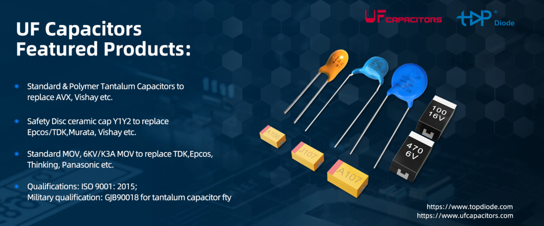
Introduction of Film and Ceramic Capacitors from UF Capacitors
UF Capacitors is an ISO9001-certified manufacturer in China, founded in 1995. We hold military qualifications for tantalum capacitors, MLCC, and other products. Additionally, we have a UL-recognized test laboratory located at our factory site.
UF Capacitors produce many types of capacitors like following to replace 1st tier brands like Murata, EPCOS, TDK, Vishay, etc with much better price and faster lead time.
#film_cap,
#ceramic_cap,
#tantalum_cap.
#Safety_capacitors
#MLCC, #SMD_aluminum_electrolytic_capacitors
For certain requirement, pls contact inquiry@ufcapacitors.com for help. There will be professional sales and engineers do cross for you.