


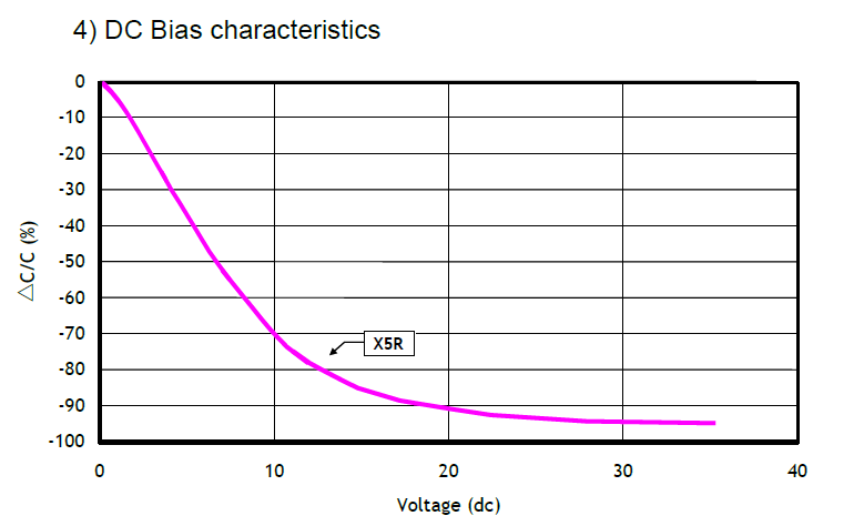
The core of MLCC DC Bias characteristics lies in how the capacitance change rate relative to the initial value (vertical axis: ΔC/C (%)) varies for MLCCs of different dielectric types when a DC voltage (horizontal axis: "Voltage") is applied. Below is a key explanation:
Horizontal axis (Voltage): The DC voltage applied across the MLCC.
Vertical axis (ΔC/C (%)): The percentage change in capacitance, calculated as [(Capacitance after change – Initial capacitance) / Initial capacitance] × 100%. A negative value means capacitance decay; the more negative the value, the worse the decay.
Each curve in the DC Bias graph corresponds to one ceramic dielectric type for MLCCs. Different dielectrics vary greatly in their sensitivity to capacitance decay under DC bias:
NP0 (also marked as C0G, red curve): Almost parallel to the horizontal axis, meaning DC bias has little impact on its capacitance (ΔC/C is close to 0). It has excellent temperature and voltage stability, making it suitable for high-frequency, high-precision scenarios (e.g., clock circuits, oscillation circuits).
X7R (green curve): Capacitance decay becomes gradual as voltage rises, but the curve is smoother than other types. It is a general-purpose dielectric that balances stability and cost, widely used in power filtering and coupling.
X5R (purple curve): Capacitance decay is more obvious than X7R. It is also a general-purpose dielectric but less stable under DC bias than X7R.
Y5V (blue curve): Most sensitive to DC bias. Even a slight voltage increase causes sharp capacitance decay (ΔC/C becomes negative quickly with a large absolute value). It has low cost but poor temperature/voltage stability, only suitable for scenarios with extremely low capacitance precision requirements (e.g., low-frequency filtering, temporary decoupling).
The graph clearly shows that dielectric type determines an MLCC’s tolerance to DC bias: "Higher-end" dielectrics (e.g., NP0) keep capacitance more stable under bias; "economic" dielectrics (e.g., Y5V) suffer worse capacitance decay.
In engineering selection, choose MLCCs with the right dielectric based on the circuit’s DC voltage level and capacitance stability requirements (e.g., NP0/X7R for high-voltage, high-stability scenarios; Y5V for low-voltage, low-precision scenarios—but always reserve margin for capacitance decay).Below is a detailed breakdown of circuit scenario-based selection and key engineering selection notes, ensuring the chosen MLCC matches performance needs while avoiding cost waste and reliability risks.
Circuits differ greatly in "DC voltage strength", "tolerance for capacitance instability", and "operating frequency". Thus, dielectrics must be selected accordingly. Here is the selection logic for 8 typical circuits:
|
Circuit Type |
Core Requirements (Closely Linked to DC Bias) |
Recommended Dielectric |
Selection Basis (with DC Bias) |
Dielectrics to Avoid/Caution |
|
1. High-frequency clock/oscillation circuits (e.g., CPU clocks, RF oscillators) |
① Capacitance precision within ±5%; ② Little capacitance decay under DC bias; ③ Stability over a wide temperature range |
NP0 (C0G) |
NP0’s DC Bias curve is near the horizontal axis (ΔC/C ≈ 0, no decay under bias) and has a temperature coefficient ≤ ±30ppm/℃, ensuring stable phase/amplitude of high-frequency signals |
X7R/X5R/Y5V (bias-induced decay causes oscillation frequency drift) |
|
2. Power filtering (e.g., DC-DC output filtering, motherboard power filtering) |
① Withstands medium DC voltage (e.g., 5V/12V/24V); ② Controllable capacitance decay under bias; ③ Balanced cost |
X7R |
X7R has a smooth DC Bias curve (ΔC/C ≈ -15% ~ -25% under 12V bias, much lower than X5R/Y5V) and a temperature range of -55℃ ~ +125℃, covering most power scenarios |
Y5V (ΔC/C ≤ -50% under 12V bias, sharply reducing filtering effect) |
|
3. Low-voltage consumer electronics coupling/decoupling (e.g., mobile phone headphone jacks, Bluetooth modules) |
① Low DC voltage (e.g., 3.3V/5V); ② Medium capacitance precision; ③ Cost optimization |
X5R |
Under low voltage (3.3V), X5R’s ΔC/C ≈ -10% ~ -20% (acceptable decay) and costs 10% ~ 20% less than X7R, suitable for mass-produced consumer electronics |
Y5V (decay may exceed -30% under low voltage, causing signal distortion) |
|
4. Low-frequency temporary filtering (e.g., power indicator circuits in toys, simple home appliances) |
① Extremely low DC voltage (e.g., 1.5V/3V); ② No capacitance stability requirements; ③ Ultra-low cost |
Y5V |
Y5V is the cheapest (40% ~ 50% lower than X7R) and has ΔC/C ≈ -20% ~ -30% under 1.5V bias, meeting basic filtering needs for low frequencies (<1kHz) |
NP0/X7R (unnecessary high cost) |
|
5. High-voltage circuits (e.g., 100V/200V power supply for industrial equipment, LED driver power) |
① Withstands high voltage (≥50V); ② Little capacitance decay under high voltage; ③ High-voltage reliability |
High-voltage NP0 or X7R (high-voltage grade) |
Ordinary X7R has ΔC/C ≈ -30% ~ -40% under 50V bias, so "high-voltage X7R" is needed (e.g., 100V rated voltage for 50V actual operating voltage, reserving bias margin). For higher stability under high voltage, choose high-voltage NP0 (ΔC/C ≈ 0) |
X5R/Y5V (decay > -60% under high voltage, even capacitor failure) |
|
6. Automotive electronics (e.g., on-board radar, ECU power supply) |
① Wide temperature range (-40℃ ~ +125℃); ② Stability under 12V/24V bias; ③ Vibration resistance/high reliability |
Automotive-grade X7R (AEC-Q200 certified) |
Automotive-grade X7R has the same DC Bias characteristics as ordinary X7R but passes reliability tests (e.g., 1000 temperature cycles, vibration tests). Its ΔC/C ≈ -15% ~ -25% under 12V bias, meeting on-board environment needs |
Ordinary X7R/Y5V (no automotive certification, prone to failure under high temperature/humidity) |
|
7. Medical equipment (e.g., monitors, ultrasound devices) |
① High stability (no decay under bias); ② Low leakage current; ③ Medical certification (e.g., UL94 V0) |
Medical-grade NP0 |
Medical equipment needs to avoid signal errors caused by capacitance decay (e.g., heart rate signals in monitors). NP0’s bias stability and low leakage current (≤10nA) meet this requirement |
X7R and below (decay may cause medical data distortion) |
|
8. RF circuits (e.g., base station antennas, WiFi 6 modules) |
① High frequency (>1GHz); ② No capacitance decay under bias; ③ Low ESR (Equivalent Series Resistance) |
High-frequency NP0 |
RF signals are extremely sensitive to capacitor "stability". NP0 has no decay under DC bias and low ESR (<0.1Ω), avoiding signal reflection/attenuation. X7R would cause impedance matching shift due to bias decay |
X7R/X5R/Y5V (decay + high ESR at high frequency, causing large signal loss) |
Selection can’t just rely on the DC Bias curve; it must be judged comprehensively based on "actual operating conditions", "circuit margin", and "reliability requirements" to avoid mistakes:
1. Always Reserve "Voltage Margin" to Avoid Bias Overstress
Core principle: MLCC’s rated voltage (VR) ≥ Actual operating voltage (Vop) × 1.2 ~ 2 (adjust based on scenarios).
Example: If the circuit’s actual operating voltage is 12V, choose X7R with 16V (12×1.33) or 25V (12×2.08) rated voltage instead of 12V. Because under 12V rated voltage, X7R’s ΔC/C will reach -30% ~ -40% (near decay limit), and long-term use may cause dielectric aging and shortened lifespan.
High-voltage scenarios (≥50V): Voltage margin must be ≥2 times (e.g., 150V rated voltage for 70V actual voltage). High voltage makes dielectric more sensitive to bias decay, and high voltage stress easily causes breakdown.
2. Consider the Superimposed Effect of "Temperature" and DC Bias
DC Bias characteristics of different dielectrics change with temperature: Higher temperature leads to worse capacitance decay under the same bias.
Example: X7R has ΔC/C ≈ -20% under 25℃, 12V, but this value increases to -35% ~ -40% under 125℃, 12V.
When selecting, confirm the circuit’s "maximum operating temperature". If temperature >85℃ (e.g., automotive engine compartments, industrial equipment), prioritize NP0. If X7R is used, further increase voltage margin (e.g., 25V rated voltage for 12V operating voltage) to offset additional decay caused by temperature.
3. Calculate "Capacitance Attenuation Compensation"
If using dielectrics with obvious decay (e.g., X5R/Y5V), reverse-calculate the capacitance based on "expected decay rate" during design to ensure the actual operating capacitance meets circuit needs.
Example: If the circuit needs a 10μF filtering capacitor and uses X5R (ΔC/C ≈ -25% under 12V bias), select a nominal capacitance of 10μF ÷ (1-25%) ≈ 13.3μF (actually choose 15μF). This avoids insufficient capacitance after bias, which would cause filtering failure.
For MLCCs with the same dielectric, capacitance, and rated voltage: Smaller package size leads to worse capacitance decay under DC bias.
Example: 0402-package X7R (10μF/16V) has ΔC/C ≈ -30% under 12V bias, while 0603-package X7R of the same specification only has -22% decay. This is because smaller packages have thinner dielectric layers, making it easier for bias to suppress domain polarization (worsening decay).
For circuits sensitive to decay (e.g., power filtering) with large capacitance (≥1μF), prioritize packages ≥0603 and avoid small packages like 0402/0201.
Forbidden Scenario 1: Use X7R or lower dielectrics in high-frequency/high-precision circuits (e.g., clocks, RF). Even under low voltage, X7R’s bias decay causes signal drift (e.g., clock frequency deviation beyond specs).
Forbidden Scenario 2: Use Y5V/X5R in high-voltage circuits (≥50V). These dielectrics have poor high-voltage stability; long-term use may cause "sudden capacitance drop" or "dielectric breakdown", leading to circuit failure.
Automotive/medical scenarios: Must use certified dielectrics (e.g., AEC-Q200 automotive-grade X7R, medical-grade NP0). Ordinary industrial-grade dielectrics have the same DC Bias characteristics but fail reliability tests, making them prone to failure in harsh environments.
For circuits with low stability requirements (e.g., low-frequency temporary filtering), Y5V is sufficient (no need for X7R). Y5V costs 40% ~ 50% less than X7R, which significantly reduces total cost in mass production.
For "low-voltage + medium-precision" circuits (e.g., consumer electronics decoupling), X5R is optimal. It costs 10% ~ 20% less than X7R and has acceptable bias decay under low voltage—there’s no need to overpursue NP0.
1.Define requirements: Confirm the circuit’s "actual operating voltage (Vop)", "maximum operating temperature (Tmax)", and "capacitance stability requirements (e.g., allowable decay, precision range)".
2.Choose dielectric: Match the dielectric to requirements (e.g., NP0 for high-voltage + high-precision; X5R for low-voltage + cost sensitivity).
3.Calculate margins: Determine rated voltage by "Vop × 1.2 ~ 2", compensate capacitance based on "expected decay rate", and adjust specs by "temperature/package" to finalize the model.
This logic ensures MLCCs maintain stable performance under DC bias while avoiding cost waste, meeting engineering needs of different circuits.
UF UF Capacitors is an ISO9001-certified manufacturer in China, founded in 1995. We hold military qualifications for tantalum capacitors, MLCC, and other products. Additionally, we have a UL-recognized test laboratory located at our factory site.
Our marketing position is to provide a superior alternative to first-tier brands such as TDK, Murata, AVX, EPCOS, Vishay, and Panasonic. We offer similar quality but at better prices, with faster lead times and excellent service. With extensive experience working with renowned international companies like GE, Philips, Jabil, and Flex, we have built a strong reputation.
UF Capacitors serves the consumer electronics, computing, communications, and industrial markets. As a professional Chinese electronic components manufacturer, we are dedicated to delivering high-quality electronic components, exceptional management, strict quality control systems, and excellent sales service. We strive to foster mutually beneficial partnerships and drive business growth.