


Cross Reference (UF vs TDK/EPCOS)
|
UF Part No. |
UF Note (from engineering list) |
TDK / EPCOS Reference |
Quick Note |
|
VAR14D102KB |
625VAC / 825VDC, RoHS, Bulk, Imax 4500A |
B72214S2621K101 (EPCOS/TDK) |
Typical 14 mm disc; standard surge rating |
|
VAR20D821KB |
510VAC / 670VDC, RoHS, Bulk, Imax 6500A |
B72220S0511K101 (EPCOS/TDK) |
20 mm disc; higher energy / surge handling |
|
VAR14D102KBQ |
625VAC / 825VDC, RoHS, Bulk, Imax 6000A |
B72214S2621K101 (EPCOS/TDK) |
Same TDK reference; UF offers higher stated Imax |
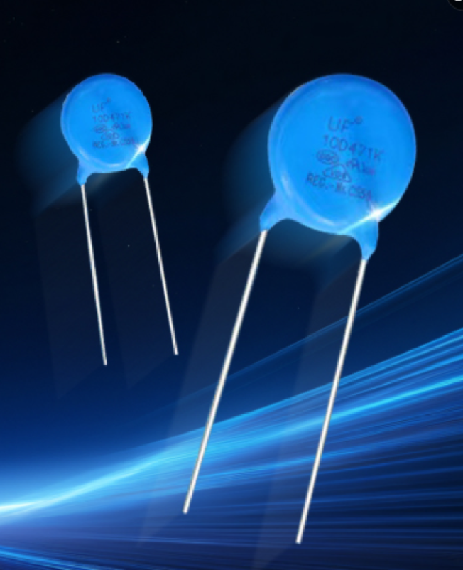
In many inverter projects, we need a small part that can take a big hit. When the grid has a spike, when a motor load switches, or when lightning couples into the line, the inverter sees a short, high-voltage pulse. If we do not control it, the stress can reach the MOSFET/IGBT, the driver IC, or the DC-link capacitor. A common solution is a varistor (often called MOV). In our list, “UF capacitors” are actually UF varistors, and we want to compare them with TDK (EPCOS) parts.
A varistor works like a voltage-dependent resistor. At normal voltage it looks almost open, so it has very small leakage. When the voltage rises above its knee point, the resistance drops fast and the varistor clamps the surge. The surge current is then diverted away from sensitive devices. After the pulse, the varistor returns to high resistance. In a real inverter, the varistor is usually placed across the AC input (L-N), sometimes L-PE, and in some designs also across the DC bus.
For a quick cross reference, our engineering matching table shows three UF part numbers and their TDK (EPCOS) equivalents. The key idea is to match the working voltage class (VAC/VDC), the varistor voltage class, and the surge capability. Only then we compare price, lead time, and supplier support.
First, let’s look at VAR14D102KB. It is marked 625VAC and 825VDC in our note, with an Imax of 4500A. It cross references to EPCOS B72214S2621K101. The “14D” normally suggests a 14 mm disc size. A 14 mm disc is a common choice when we need a compact footprint but still want decent energy handling. This type is often used for medium power inverter input, where surges exist but are not extreme.
Second, VAR20D821KB is 510VAC / 670VDC with Imax 6500A and cross references to EPCOS B72220S0511K101. The “20D” indicates a larger 20 mm disc. A larger disc generally means higher energy absorption and higher surge current capability. If the inverter is installed in an environment with more frequent surges, or if the system standard demands a stronger surge level, a 20 mm varistor is often safer. The trade-off is more space and sometimes higher cost.
Third, VAR14D102KBQ uses the same TDK reference (B72214S2621K101) but the UF note says Imax 6000A instead of 4500A. In practice, this kind of difference is exactly why we should not only read the short line in a BOM. We should compare the official datasheet definitions: some vendors quote an 8/20 µs pulse, some quote a different waveform, and some quote a single hit vs. repeated hits. If the waveform or test method is not the same, the numbers are not directly comparable.
For inverter use, it helps to remember what the ratings mean in simple terms. VAC/VDC rating is the continuous working voltage. We choose it so that at normal line or bus voltage the varistor is not conducting. Varistor voltage (often written as V1mA) is the point measured at a small test current. It tells us where the clamp action starts. Clamping voltage under surge is higher than varistor voltage, and that is what the inverter devices really see. Surge current (Imax) and energy ratings tell us how much abuse the part can take without failing.
When a varistor fails, it often fails short after many surges or after one severe surge. In an inverter, a shorted MOV can overheat and can even burn if it is not protected. So, for safety, many designs add a series fuse, a thermal fuse, or choose a MOV with an integrated thermal disconnect. This is not only a reliability topic, it is also a compliance topic for some safety standards.
Now, how do we compare UF versus TDK (EPCOS) in a practical way? TDK (EPCOS) is a large global supplier. Their datasheets are usually detailed, with clear curves for leakage, capacitance, varistor voltage tolerance, and surge life tests. Traceability and long-term consistency are strong points. For customer projects that require a well-known brand, or for markets with strict approval needs, TDK can reduce risk.
UF can be attractive when we need better cost, faster delivery, or local support. Sometimes UF offers a part that looks like a direct drop-in replacement, and in many cases it may work well. But we should still verify three things: (1) electrical match (working voltage and clamp level), (2) surge durability (repeated surge test, not only one-time Imax), and (3) process quality (aging control, batch consistency, RoHS records). If these are confirmed, UF can be a good second source for the same inverter platform.
For the three items in our table, the selection logic can be simple. If the design needs 625VAC class and space is limited, VAR14D102KB (or its TDK equivalent) is a common baseline. If surge level is higher, the 20 mm option VAR20D821KB may give a bigger safety margin. For VAR14D102KBQ, we should treat it as the same voltage class as VAR14D102KB, but check the test standard behind the higher Imax claim. If the waveform and surge life are proven, it could be a stronger 14 mm choice.
A good engineering habit is to confirm the final choice with two quick checks: First, run the worst-case voltage and temperature to ensure leakage stays low (so the MOV does not heat in normal operation). Second, check that the clamping voltage under the expected surge is below the maximum stress limit of the MOSFET/IGBT and the driver. If possible, do a simple surge test on the full inverter board. This gives more confidence than paper matching alone.
In summary, UF varistors can be matched to TDK (EPCOS) types for inverter surge protection when voltage class and surge capability align. TDK provides strong documentation and stable quality, which is helpful for risk control. UF may offer cost and lead-time benefits, but it should be validated with the same waveform and life test method. With a clear cross reference and a short verification plan, we can protect the inverter well and also keep the supply chain flexible.