


Derating means:
Operating the capacitor at a voltage significantly lower than its rated voltage — typically 50% or less.
Example:
The circuit runs at 5V. Instead of choosing a 6.3V MLCC, you select a 16V or 25V part.
This is not "over-engineering" — it's necessary to ensure effective capacitance.
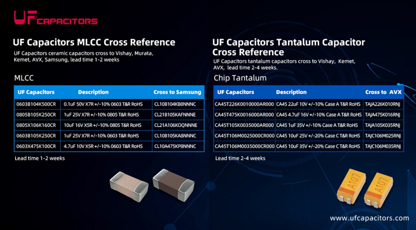
What Is the DC Bias Effect?
For Class 2 ceramic capacitors (X7R, X5R, Y5V, etc.), applying a DC voltage causes the effective capacitance to drop significantly.
This is a physical property of the ceramic material, not a quality defect.
How Severe Is It?
|
Rated Voltage |
Actual Working Voltage |
Remaining Effective Capacitance (Typical) |
|
10V |
10V |
30% ~ 50% |
|
10V |
5V |
60% ~ 80% |
|
10V |
3.3V |
80% ~ 90% |
|
16V |
5V |
85% ~ 95% |
Real-World Example
A 10V / 10µF X7R MLCC may only provide 6µF at 5V, and only 3~4µF at 10V.
Using a 25V-rated capacitor of the same capacitance, at 5V you can retain over 9µF.
|
Application Scenario |
Recommended Derating Ratio |
|
Power filtering / Bulk storage |
50% or lower (e.g., 12V → 25V) |
|
General decoupling |
60% ~ 70% |
|
High reliability (Automotive, Industrial) |
20% ~ 30% (aggressive derating) |
|
Class 1 (C0G/NP0) |
Little or no derating needed |
Working Voltage ≤ Rated Voltage × 0.5
That is:
5V circuit → choose 10V or higher (16V / 25V recommended)
12V circuit → choose 25V or 50V
24V circuit → choose 50V
Increased power ripple
Poor chip decoupling → possible resets or erratic behavior
Degraded EMI/EMC performance
DC bias doesn't directly accelerate aging, but with already reduced capacitance margin, further aging over time can push the system to the edge of failure.
Higher electric field stress inside the MLCC increases the risk of short-circuit failure, especially for larger case sizes.
Many engineers check only "rated voltage > working voltage" and ignore the DC bias effect.
Correct approach: Always check the actual effective capacitance at your working voltage.
C0G/NP0: DC bias effect is tiny — little or no derating needed.
X7R / X5R: Must be derated.
Excessive derating (e.g., using a 100V cap for a 5V circuit) leads to:
Larger footprint
Higher cost
Lower available capacitance for the same case size
Recommendation: Derate to 50%~30% of rated voltage — no need to go extreme.
|
Working Voltage |
Recommended MLCC Voltage Rating (Class 2) |
|
1.8V |
6.3V or 10V |
|
3.3V |
10V or 16V |
|
5V |
16V or 25V |
|
12V |
25V or 50V |
|
24V |
50V |
|
48V |
100V |
In space-constrained applications (smartphones, wearables), larger high-voltage packages may not fit.
Use the same voltage rating but a larger case size
Example: 0402 10V → 0603 10V — DC bias performance improves.
Switch to C0G/NP0
If capacitance is low ( <10nF ), C0G eliminates the DC bias issue entirely.
Use multiple MLCCs in parallel
Helps distribute voltage stress, but improvement is limited.
Switch to tantalum or polymer capacitors
But note: tantalum also requires derating (even more aggressively than MLCC).
For Class 2 MLCCs (X7R/X5R), never operate above 50% of rated voltage — otherwise effective capacitance collapses.
5V circuit → at least 10V, ideally 16V/25V
12V circuit → 25V minimum
C0G capacitors need little or no derating