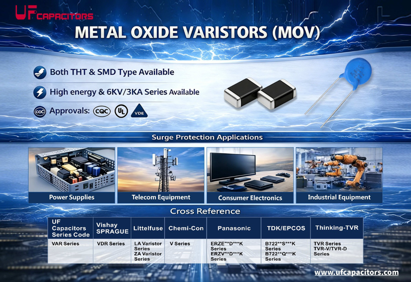


What Is a Metal Oxide Varistor (MOV)?
A Metal Oxide Varistor is a voltage-dependent, nonlinear resistive device. It is primarily made from zinc oxide (ZnO) grains and small amounts of other metal oxide additives, sintered at high temperatures. Its core electrical characteristics are:
This unique nonlinear voltage-current characteristic makes the MOV an ideal choice for suppressing abnormal over-voltage in circuits and protecting sensitive downstream components.
Basic Working Principle of an MOV
Microstructure and Conduction Mechanism
An MOV has a complex polycrystalline structure composed of zinc oxide grains and grain boundary layers. A potential barrier, similar to a bidirectional PN junction, forms between adjacent ZnO grains:
This process is repeatable. However, each surge impact causes gradual stress accumulation on the grain boundaries, ultimately leading to device aging.
Voltage-Current (V-I) Characteristic Curve
The V-I characteristic of an MOV can be divided into three operating regions:
|
Region |
Voltage State |
Current State |
Description |
|
Leakage Region |
Below rated voltage |
Microamps (µA) |
High impedance, almost no current flow |
|
Nonlinear Region |
Near rated voltage |
Milliamps to kiloamps |
Small voltage change, large current change, best clamping effect |
|
Saturation Region |
Significantly above rated voltage |
Extremely high current |
Linear resistor behavior, may lead to thermal runaway damage |
In design applications, the MOV should operate within the nonlinear region to avoid entering the saturation region, which could cause overheating and destruction.
Important Parameters When Selecting an MOV
Key Technical Specifications
Engineers usually evaluate the following core parameters when selecting an MOV:
|
Parameter |
Symbol |
Description |
Typical Range |
|
Varistor Voltage |
V₁mA |
Voltage across the device at 1mA DC current |
18V ~ 1800V |
|
Max. Continuous Operating Voltage |
Vᵢ (AC/DC) |
Max. AC/DC voltage that can be applied continuously |
14V ~ 750V AC |
|
Max. Clamping Voltage |
VCLAM |
Voltage across the MOV at a specified surge current |
Related to V₁mA |
|
Peak Surge Current |
Iₚ (8/20µs) |
Max. single 8/20µs waveform surge current capability |
100A ~ 70kA |
|
Rated Energy |
E (10/1000µs) |
Max. single-pulse energy absorption capability |
Few joules to hundreds of joules |
|
Leakage Current |
Iₗ |
Leakage current at max. continuous operating voltage |
< 20µA |
Selection Calculation Formula
Varistor Voltage Calculation:
For an AC circuit: V₁mA ≥ 2.2 × Vnom (Vnom is the RMS AC voltage)
Or V₁mA ≥ 1.5 × Vp (Vp is the peak voltage)
Example: For a 220V AC power system
Max. Allowable Voltage Verification:
Surge Current Capability Calculation:
When the surge test voltage level is known:
Iₚ = (Vtest - VCLAM) / 2
In practice, select a MOV with a surge current rating at least 3 times higher than the calculated requirement to ensure reliability after multiple surges.
Package Specifications and Naming Conventions
The MOV's package diameter is directly related to its surge current capability:
|
Model Series |
Diameter (mm) |
Peak Surge Current Range |
Typical Applications |
|
5D Series |
5 |
100A ~ 400A |
Low-power, small supplies |
|
7D Series |
7 |
500A ~ 1750A |
Chargers, adapters |
|
10D Series |
10 |
500A ~ 2500A |
LED drivers, switching supplies |
|
14D Series |
14 |
1000A ~ 4500A |
Industrial supplies, appliances |
|
20D Series |
20 |
2000A ~ 6500A |
Power meters, telecom equipment |
|
25D+ Series |
25+ |
4500A ~ 15000A |
Surge protective devices (SPDs), distribution systems |
Naming Rule Example (471KD14):
Typical MOV Application Circuit
Basic Application Topology
An MOV is typically connected in parallel between the live (L) and neutral (N) lines at the power input, or between the line and ground. Its typical location is after the fuse and before the bridge rectifier or switching power supply.
plaintext
AC Input ──┬── Fuse ──┬── MOV ──┬── Downstream Circuit (Bridge Rectifier / Power Supply)
│ │ │
└────────────┴─────────┘
│
Ground (Optional)
Integrated Protection Solutions
To improve protection reliability and safety, MOVs are often used together with the following components:
Example of Integrated Device : Some manufacturers integrate a PPTC (Polymeric Positive Temperature Coefficient) resettable fuse with an MOV, providing resettable protection under both over-voltage and over-current conditions.
Advantages and Limitations of MOVs
Key Advantages
Limitations and Mitigation Measures
|
Limitation |
Description |
Mitigation |
|
Leakage Current |
Microamp leakage current exists during normal operation |
Pay special attention in ultra-low-power designs |
|
High Capacitance |
Hundreds to thousands of pF, affects high-frequency signals |
Not suitable for high-frequency signal lines; use MLV or TVS instead |
|
Aging Failure |
Performance degrades after multiple surge events |
Design with sufficient margin; use with thermal protection |
|
High Clamping Voltage |
Can be 1.5-2 times the varistor voltage |
Ensure downstream circuits have sufficient voltage margin |
Common Failure Modes and Thermal Runaway Protection
Two Main Failure Modes
1.Progressive Aging Failure (Most Common):
Repeated surge impacts damage grain boundaries; varistor voltage gradually decreases.
When varistor voltage drops below the peak normal grid voltage, the MOV enters a continuous conduction state.
Continuous AC current flow causes thermal runaway and eventual burnout.
2.Instantaneous Overstress Failure (Less Common):
A single, extremely large surge (e.g., direct lightning strike) exceeds the MOV's absolute rating.
The MOV is instantly punctured or cracked, typically failing as a short circuit.
Thermal Runaway Protection Mechanisms
To prevent fire hazards from a failing MOV, protection circuits should incorporate:
Introduction to Multilayer Varistors (MLVs)
For low-voltage, high-frequency signal line ESD protection, Multilayer Varistors (MLVs) are often a more suitable choice:
|
Feature |
MOV |
MLV |
|
Structure |
Single-layer disc |
Multilayer SMD |
|
Response Speed |
Nanoseconds |
Sub-nanoseconds |
|
Capacitance |
Higher (pF-nF) |
Lower (pF range) |
|
Application |
Power lines, high-energy surges |
Signal lines, ESD protection |
|
Typical Use Cases |
AC input, lightning protection |
USB2.0, HDMI, GPIO |
MLVs are suitable for data ports up to 480Mbps, such as USB2.0, computer peripherals, digital cameras, and mobile phones.
Common MOV Application Problems
To improve protection, MOVs are often used together with:
MOV Solutions from Topdiodes
Topdiodes provides a wide range of Metal Oxide Varistors for over-voltage protection in consumer, industrial, and power electronics applications.
Product Range Includes:
Key Benefits:
Recommended Applications:
|
Application Area |
Recommended Series |
Key Parameters |
|
Chargers/Adapters (5-20W) |
7D Series |
470V, 500-1750A |
|
LED Driver Power Supplies |
10D/14D Series |
470-680V, 2500-4500A |
|
Industrial Switching Supplies |
14D/20D Series |
470-820V, 4500-6500A |
|
Home Appliance Control Boards |
10D/14D Series |
270-470V |
|
Surge Protective Devices (SPD) |
25D+ Series |
470-820V, 10kA+ |
|
Signal Line ESD Protection |
MLV Series |
Low capacitance, fast response |